 Image unavailable. The source caption, original image link and project text remain available.
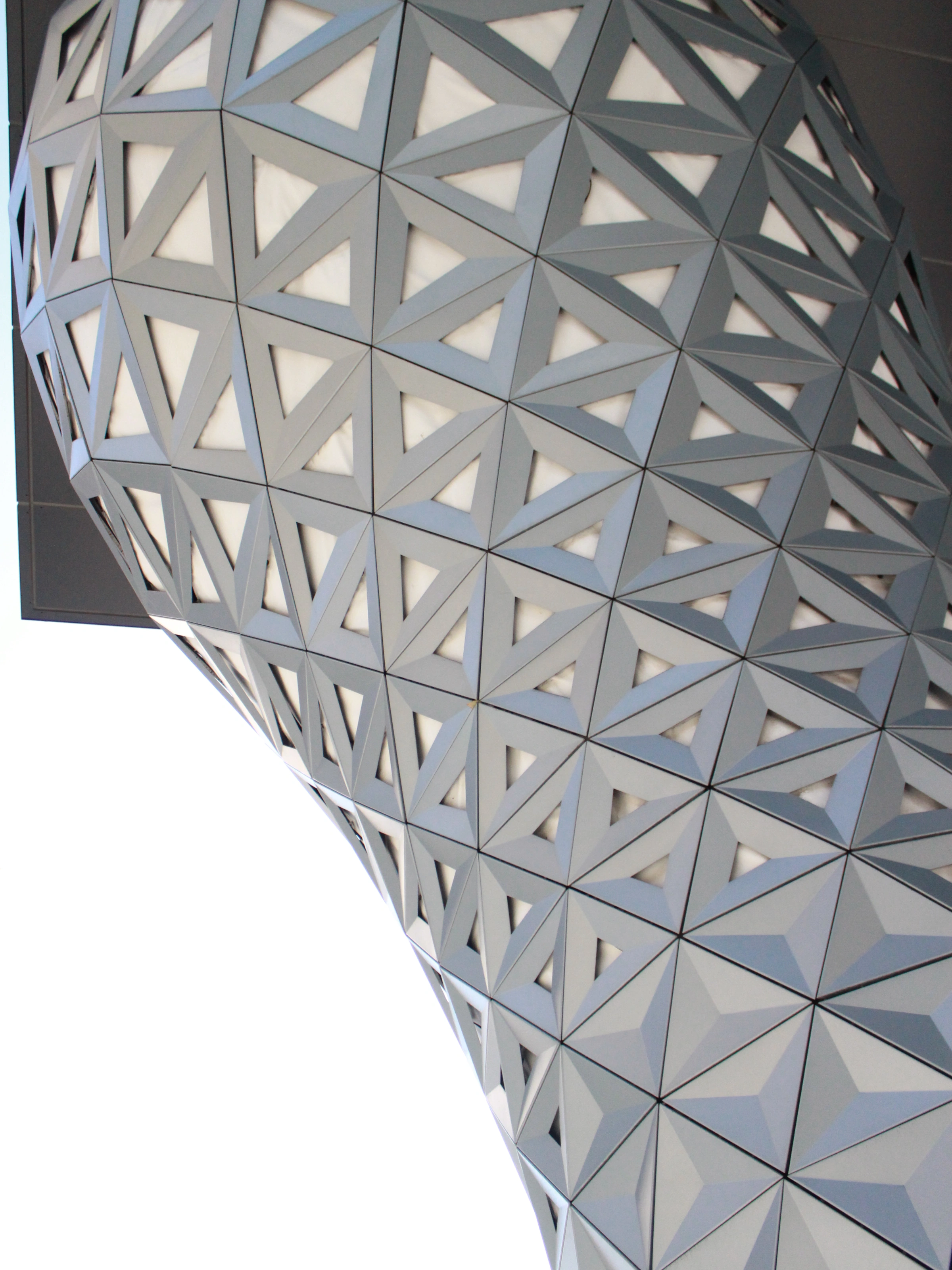
The folded panel surface of the Taichung Nan Shan no.6 Square entrance installation.
Project: PKD Engineering Consultants.Open full image (new tab)Taichung Nan Shan no.6 Square
I helped turn a patterned entrance installation into coordinated 3D models and fabrication drawings within the PKD engineering team.
Follow the study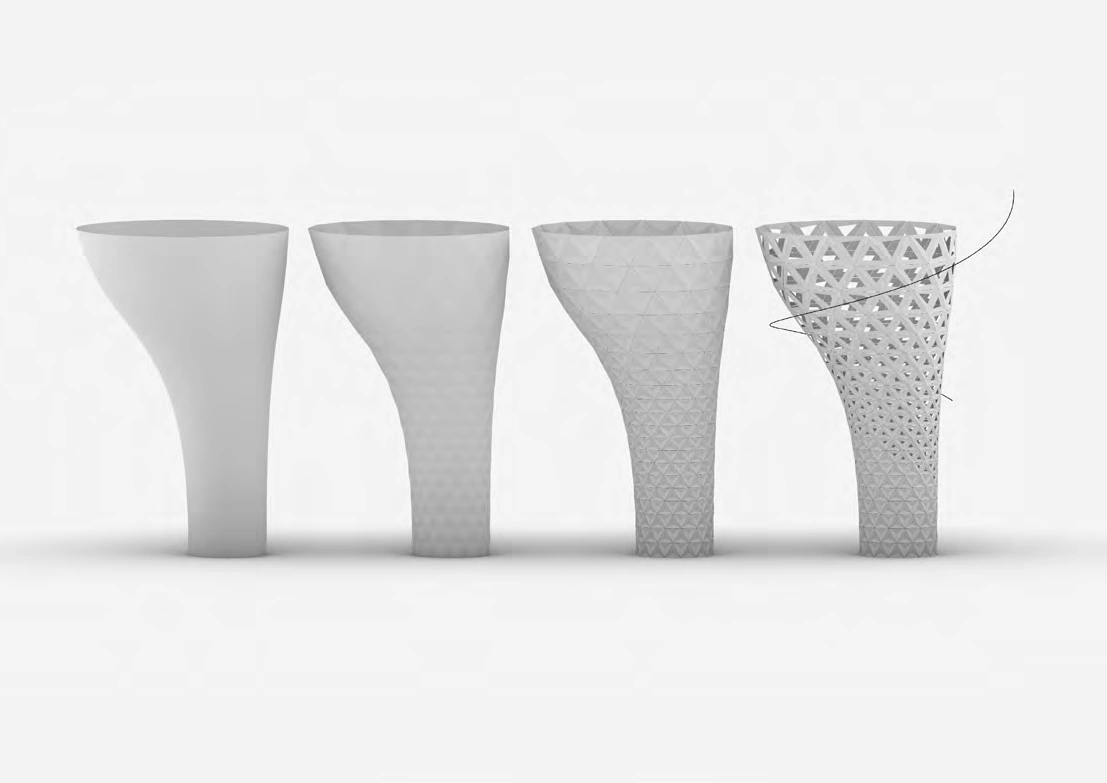
Original source view.
Scheme model of the folded-panel installation, with its connections, supports, core and base.
Scroll to follow the camera. With focus, use arrow keys to inspect; Home or Esc returns to the current scroll view.
Surface subdivision, panel depth and a helical distance field develop the pattern.
Project: PKD Engineering Consultants.
Develop the surface, then its openings.
I worked within the PKD team to develop an entrance installation from a continuous surface into individually defined folded panels.
The original study moves from a smooth surface through subdivision and panel depth to openings. Read these four states before comparing the alternative pattern schemes below.
Read the four surface states
Reading guide over the original raster plate. Outlines mark areas of attention, not new geometry. All source labels remain in the complete image.
Select the numbered areas in order, or return to the complete plate at any time. The original image is never cropped or obscured.
Begin with the smooth overall surface at the left of the original study.
The second model introduces the triangular subdivision on the same overall form.
The third model makes the triangular panel depth visible.
The final model introduces openings; the original helical guide remains visible beside it.
Surface subdivision, panel depth and a helical distance field develop the pattern.
Project: PKD Engineering Consultants.
Open complete source image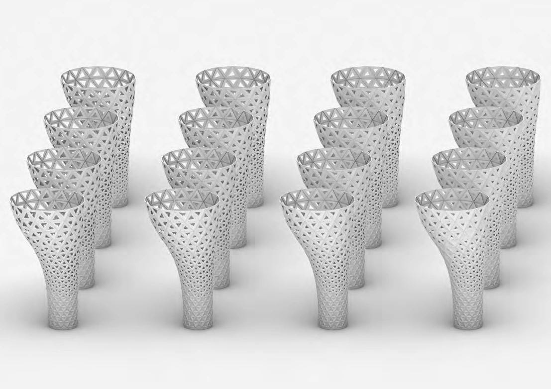
Pattern schemes developed within the same overall installation geometry.
Project: PKD Engineering Consultants.Open full image (new tab)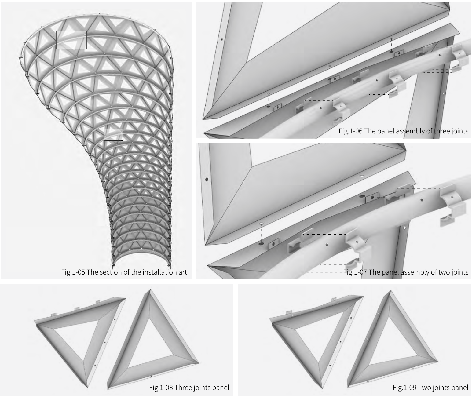
Original source view.
Scheme model of the folded-panel installation, with its connections, supports, core and base.
Scroll to follow the camera. With focus, use arrow keys to inspect; Home or Esc returns to the current scroll view.
The support system and the two families of folded panel connections.
Project: PKD Engineering Consultants.
Connect the surface to its panel joints.
My modelling work connected the triangulated surface with panel depth, opening patterns and a shared reference system. These relationships let local variation remain coordinated with the overall installation.
The source plate relates the overall support section to three-joint and two-joint panel assemblies. Compare those details with the two folded-panel families before moving to their fabrication information.
From the support section to a panel
Reading guide over the original raster plate. Outlines mark areas of attention, not new geometry. All source labels remain in the complete image.
Select the numbered areas in order, or return to the complete plate at any time. The original image is never cropped or obscured.
Fig. 1-05 locates the panel surface and supporting structure together.
Fig. 1-06 shows the exploded relationship for the three-joint panel assembly. This is the original illustration, not a new assembly simulation.
Fig. 1-07 shows the corresponding two-joint panel assembly.
Fig. 1-08 isolates the folded three-joint panel family.
Fig. 1-09 isolates the folded two-joint panel family.
The support system and the two families of folded panel connections.
Project: PKD Engineering Consultants.
Open complete source image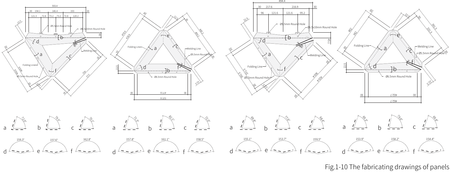
The model is translated into dimensioned fabrication drawings for individual panels.
Project: PKD Engineering Consultants.
Translate the model for fabrication.
I translated the 3D panel geometry into fabrication drawings, bringing together fold angles, holes, tabs and reference information.
Read the dimensioned panel outlines alongside their lettered folding-angle details. Model-derived information and manual checks were coordinated with the fabrication team; the workshop photographs below document separately fabricated modules and internal supports.
Read the drawing with its angle details
Reading guide over the original raster plate. Outlines mark areas of attention, not new geometry. All source labels remain in the complete image.
Select the numbered areas in order, or return to the complete plate at any time. The original image is never cropped or obscured.
The upper row retains the original dimensions, hole notes, folding lines and welding lines. Open the full image to inspect the small source lettering.
The lower rows retain the original a–f angle details associated with the panel drawings above. These values are source information, not recalculated instructions.
The model is translated into dimensioned fabrication drawings for individual panels.
Project: PKD Engineering Consultants.
Open complete source image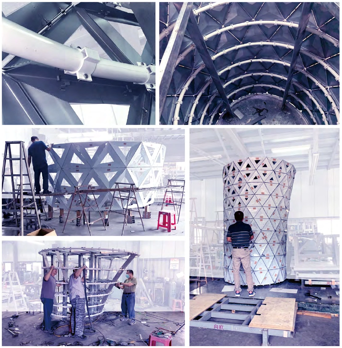
Workshop documentation of the internal supports and separately fabricated modules.
Project: PKD Engineering Consultants.Open full image (new tab)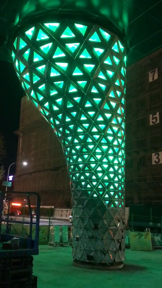
The built installation during a night lighting sequence.
Project: PKD Engineering Consultants.
Read the assembled geometry.
The completed surface brings the variation of individual openings into a continuous entrance installation. Close views reveal folds, edges and the relationship between neighbouring panels.
My contribution covered scheme development, 3D modelling and fabrication drawings within the wider engineering, fabrication and installation team.
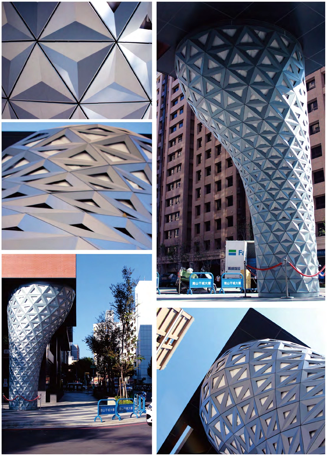
Built surface details and the entrance installation in its site context.
Project: PKD Engineering Consultants.Open full image (new tab)